


Consistent Comfort and Optimal Airflow for HVAC Consultants

Table of Contents
Why Consistent Comfort and Optimal Airflow Matter for HVAC Consultants
How to Improve HVAC Airflow: Core Assessment Methods
Static Pressure Measurement and CFM Verification
Supply and Return Air Evaluation
HVAC Airflow Balancing: Diagnostic Decision Trees and Procedures
Room-to-Room Temperature Mapping
Register and Damper Adjustment Protocols
Duct Leakage Testing: Identifying and Quantifying Air Loss
Blower Door and Duct Pressurization Standards
Sealing Strategies and Performance Targets
HVAC System Commissioning: From Design to Verified Performance
Equipment Selection and Capacity Calculations
Startup Verification and Documentation
Ventilation, Filtration, and Indoor Air Quality Trade-Offs
How Filtration Loads the Fan
Ventilation Rates and the Cost of Fresh Air
The Trade-Off Framework
Where Consultants Get This Wrong
Title 24 Compliance and Energy Efficiency Standards
The Standards Stack You Actually Work Against
Documented Performance Targets and Acceptance Criteria
The Commissioning Report as a Legal and Professional Record
Where Consultants Add the Most Value
Common Airflow Problems and How to Diagnose Them
Frequently Asked Questions
Last Updated: October 14, 2026
Why Consistent Comfort and Optimal Airflow Matter for HVAC Consultants
Consistent comfort and optimal airflow for HVAC consultants is measurable performance that satisfies occupants, meets regulations, and prevents callbacks. Proper airflow assessment separates projects that pass inspection from those that create disputes months after handoff.
The problem is invisible until someone complains: a system may appear to work at startup, but uneven temperatures, stale air, or high energy use reveal design flaws, installation defects, or inadequate commissioning that went undiagnosed because nobody measured the system.
Consistent comfort and optimal airflow for HVAC consultants requires knowing what to measure, how to diagnose problems, and having a documented process that proves the system performs as designed. This guide covers the assessment methods, balancing procedures, and commissioning standards that turn a guessed-at installation into a verified, compliant system.
How to Improve HVAC Airflow: Core Assessment Methods
Improving HVAC airflow starts with measurement: core assessment methods establish a baseline, identify restrictions, and guide fixes.

Static Pressure Measurement and CFM Verification
Static pressure is the resistance to airflow within ductwork. Elevated readings indicate restrictions: undersized ducts, clogged filters, blocked registers, or leaks.
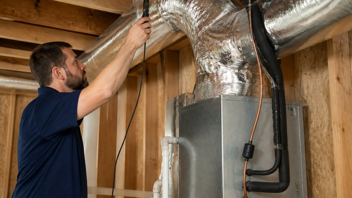
Use a digital manometer at the air handler's return and supply plenums and compare to equipment specs.
CFM verification confirms the system delivers design airflow.
Supply and Return Air Evaluation
Supply and return capacity must balance. A common mistake is undersizing return ductwork relative to supply, creating negative pressure that draws unconditioned air through wall cavities and gaps.
Walk the system and note register locations, duct sizing, and visible restrictions.
Measure supply air temperature at key registers. Significant variation, one room at 68°F while another reads 75°F, reveals imbalanced distribution and guides your balancing strategy.
HVAC Airflow Balancing: Diagnostic Decision Trees and Procedures
Balancing is systematic adjustment of dampers and registers to achieve even temperature distribution and consistent comfort and optimal airflow for HVAC consultants across all spaces.
Small Business Celebration
Room-to-Room Temperature Mapping
Map temperatures throughout the building at multiple times of day with an infrared or calibrated digital thermometer, recording at the center of each room away from sunlight, drafts, or equipment.
Log room names, target temperatures, and measured temperatures in a spreadsheet, then look for patterns: are upper floors consistently warmer? Do corner rooms lag?
If one zone runs 3-5°F warmer or cooler than others, its supply damper likely needs adjustment.
Register and Damper Adjustment Protocols
Adjust supply registers incrementally: close registers in overconditioned spaces by 25-50%, then remeasure after 30 minutes. Document each adjustment.
For internal dampers, locate them at the main supply trunk and each branch and adjust proportionally from the temperature mapping data.
Record damper positions as percentages or marked positions (e.g., "Master damper 75% open, east zone damper 50% open") so no one resets your work and future technicians understand the configuration.
Duct Leakage Testing: Identifying and Quantifying Air Loss
Duct leaks waste energy and degrade performance. A system with significant leakage cannot deliver design airflow no matter how well you balance registers, so quantifying leakage guides repair priorities.
Blower Door and Duct Pressurization Standards
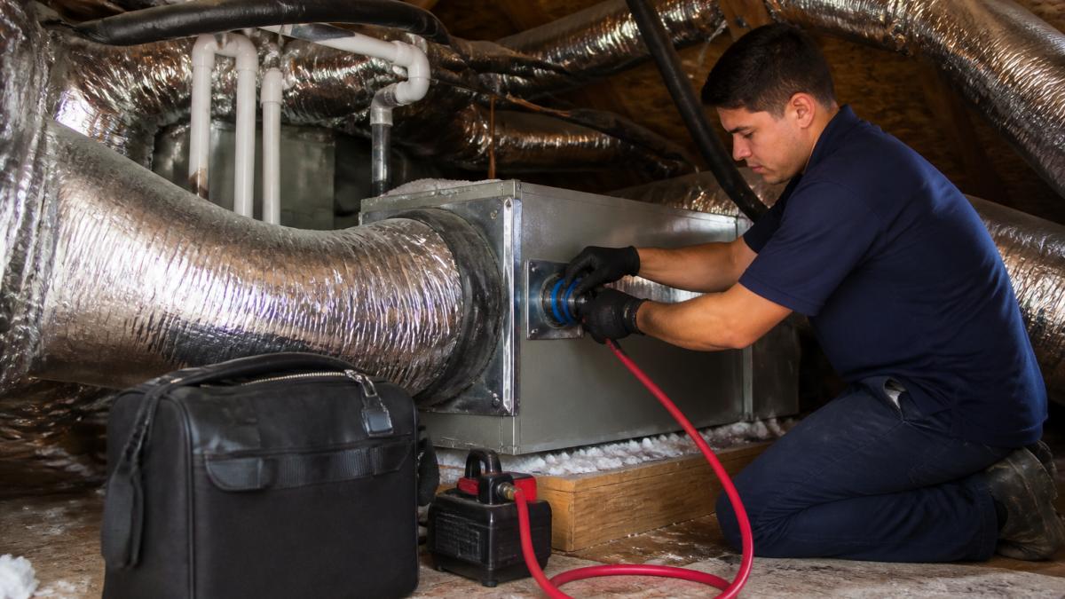
Duct leakage is measured by pressurization: seal the return side, pressurize the supply ductwork to 25 pascals, and measure the airflow required to hold that pressure.
Codes cap allowable leakage, typically at 15% of system airflow. For a 2,000 CFM system, that's 300 CFM25.
Document the test procedure, equipment used, and measured leakage. This data justifies repairs and proves compliance with energy codes.
Sealing Strategies and Performance Targets
Start with accessible leaks: air handler connections, register boots, and return plenums. Use mastic sealant and mesh tape, since duct tape deteriorates within years. Seal visible gaps in attics and crawlspaces.
Retest after sealing to confirm improvement; a drop from 450 to 200 CFM25 is significant progress.
HVAC System Commissioning: From Design to Verified Performance
Commissioning verifies that a system operates as designed, bridging installation and long-term performance and catching problems before they become complaints.
Equipment Selection and Capacity Calculations
Commissioning begins with design. Calculate loads using ACCA Manual J or equivalent.
Match equipment capacity to the calculated load. A 3-ton system serving a 2.5-ton load short-cycles inefficiently; a 2-ton system serving a 3-ton load struggles at peak.
Document the load calculation and equipment selection so commissioning can verify the installed equipment delivers rated capacity under site conditions.
Startup Verification and Documentation
On startup, measure supply and return air temperatures and system runtime, calculate sensible capacity, and compare to equipment ratings. Document everything in a commissioning report.
Verify thermostat setpoints, fan speed, and control sequences match design intent, and that safety interlocks function, such as shutdown on excessive static pressure or low return air temperature.
Create a handover document explaining system operation, maintenance intervals, and filter schedules.
Ventilation, Filtration, and Indoor Air Quality Trade-Offs
Airflow, ventilation, and filtration are three demands on the same fan, and every decision on one changes the other two. Consultants who treat them independently deliver systems that meet one target and miss the others.
How Filtration Loads the Fan
Filter pressure drop is the most under-modeled variable in residential and light commercial design.
MERV, defined by ASHRAE Standard 52.2, rates particle capture by size (Debunking Myths About MERV, Air Filtration).
A filter adding 0.3 inches of pressure drop to a system already at 0.7 inches total external static pressure pushes the air handler past its rated maximum.
Key Takeaway Always select the filter cabinet and filter together with the air handler's expanded performance data in hand. A filter that meets the IAQ goal but exceeds the static pressure budget is not a solution, it is a callback.
Ventilation Rates and the Cost of Fresh Air
That outdoor air is not free. In a humid climate, 60 CFM of 90°F, 75°F dew point air adds a latent load; in a cold climate it adds a sensible heating load.
ASHRAE Standard 62.1 governs commercial ventilation using a breathing zone outdoor airflow rate based on occupancy category and floor area, adjusted by zone air distribution effectiveness.
The Trade-Off Framework
When ventilation, filtration, and airflow targets conflict, work through them in this order:
Establish the airflow budget. Start with the air handler's rated CFM at design static pressure, then subtract for the filter, coil, duct system, and accessories. What remains is what you can deliver.
Set the ventilation target. Determine required outdoor air CFM from the applicable ASHRAE standard or code, and decide whether it will be continuous or intermittent and conditioned by the main system or a dedicated outdoor air system.
Set the filtration target. Choose the MERV or MERV-A rating based on occupant sensitivity, outdoor air quality, and program requirements, then verify clean and loaded pressure drop fits the remaining static pressure budget.
Verify the envelope. A tight envelope reduces infiltration and increases the importance of mechanical ventilation; a leaky envelope provides uncontrolled ventilation you cannot measure, filter, or condition.
Document the design intent. Record target CFM, filter specification, ventilation rate, and assumed envelope leakage. These become the acceptance criteria for commissioning.
Where Consultants Get This Wrong
The most common failure is specifying a high-MERV filter for IAQ without re-checking the air handler's static pressure budget. The second is installing ventilation that meets the ASHRAE rate on paper but delivers less in the field because the intake duct is undersized or the damper mis-set.
A consultant who walks an owner through airflow, ventilation, and filtration trade-offs with numbers, not adjectives, delivers something no filter-change reminder can replace.
Title 24 Compliance and Energy Efficiency Standards
Compliance is not one code you memorize once. It is a stack of federal, state, and local requirements plus voluntary standards defining "verified performance." Consultants who treat it as a checkbox miss the documentation trail that protects them when a system underperforms after handoff.
The Standards Stack You Actually Work Against
Federally, the U.S. Department of Energy sets minimum efficiency standards through the Appliance and Equipment Standards Program, with regional minimums by climate zone.
State and local adoption varies widely.
Voluntary standards fill code gaps: ASHRAE 62.1 and 62.2 define ventilation rates, ASHRAE 55 defines thermal comfort, ACCA Manuals J, S, and D define load calculation, equipment selection, and duct design, and SMACNA standards define fabrication and sealing classes.
Pro Tip Before you quote a project, pull the adopted code edition for that jurisdiction. Two neighboring cities can enforce different IECC editions with different duct leakage thresholds and different commissioning requirements.
Documented Performance Targets and Acceptance Criteria
The consultant's deliverable is not a working system but evidence that it meets defined targets.
A workable acceptance criteria set typically includes:
Design airflow per zone, in CFM, from the load calculation and equipment selection.
Total external static pressure, against the air handler's rated maximum from expanded performance data.
Duct leakage, as CFM25 and a percentage of design airflow, against the adopted code or program threshold.
Each criterion needs a measurement method, instrument, and tolerance. "Airflow is adequate" is not a criterion; "Zone 3 delivers 320 CFM ±10% at design static pressure, measured with a calibrated flow hood" is.
The Commissioning Report as a Legal and Professional Record
A commissioning report is the artifact that survives the project. It should contain design intent, measured results, instruments with calibration dates, ambient test conditions, and any deviations with corrective action. Sign, date, and deliver a copy to the owner.
This matters for three reasons: many code editions and utility programs require the report for final inspection or rebate payment; it establishes a baseline future technicians can measure against, preventing a later contractor from "fixing" a system by undoing the original balance; and when a comfort complaint arrives eighteen months after handoff, it is the difference between a documented dispute and an unwinnable argument about what was promised.
Watch Out Do not backfill a commissioning report after the fact. Measured values recorded without the actual test conditions and instrument calibration data carry little weight in an inspection dispute or a warranty claim.
Where Consultants Add the Most Value
The gap between a code-compliant installation and a verified one is measurement discipline. Most contractors install to code and assume it works. The consultant defines acceptance criteria up front, verifies each with a documented method, and hands over a report proving the system performs as designed.
Common Airflow Problems and How to Diagnose Them
Most airflow problems fall into a few categories.
Uneven temperatures across rooms: Start with temperature mapping.
Low airflow at some registers: Confirm reduced velocity with an anemometer.
High energy bills with normal temperatures: Measure static pressure.
Each problem requires measurement to confirm the diagnosis. Guessing leads to expensive, unnecessary repairs and continued complaints.
Consistent comfort and optimal airflow for HVAC consultants demands more than installation skill: it requires systematic assessment, precise balancing, and documented verification. Central Duct Testing brings certified expertise and state-of-the-art equipment to every project, ensuring maximum energy efficiency, Title 24 compliance, and consistent comfort year-round.
Frequently Asked Questions
How do HVAC consultants measure and verify optimal airflow in a system?
Consultants use static pressure measurements, CFM (cubic feet per minute) verification with anemometers, and blower door testing to quantify airflow. Static pressure should stay within manufacturer specifications; typical targets are 0.05 to 0.10 inches of water column across the system. Supply and return air measurements confirm the air handler is delivering design capacity, while duct leakage tests measure total system losses against Title 24 and energy code requirements.
What is HVAC airflow balancing and why is it critical for consistent comfort?
HVAC airflow balancing redistributes air between rooms by adjusting dampers and registers to match design intent and occupant comfort needs. Without balancing, some rooms become too hot or cold while others stay comfortable. Consultants use temperature mapping and pressure diagnostics to identify imbalances, then adjust each branch of the ductwork to deliver the correct CFM to each space, ensuring thermal comfort throughout the building.
How does duct leakage affect energy efficiency and what testing standards apply?
Duct leakage allows conditioned air to escape into unconditioned spaces, wasting energy and forcing the system to work harder to maintain temperature. Title 24 and IECC codes set maximum leakage limits; most residential systems must achieve 10% or less duct leakage relative to total airflow. Duct pressurization testing quantifies this loss, and sealed ducts can reduce energy consumption by 10-20% while improving comfort and system longevity.
What is HVAC system commissioning and how does it differ from routine maintenance?
Commissioning is a comprehensive verification process that confirms a system meets design specifications from startup through initial operation. It includes capacity verification, airflow testing, control sequence checks, and documented performance benchmarks. Routine maintenance addresses ongoing upkeep. Commissioning catches design and installation errors early, prevents comfort complaints, ensures code compliance, and establishes a baseline for energy management and future troubleshooting.
What are common causes of poor airflow and uneven temperatures in residential HVAC systems?
Common causes include oversized or undersized equipment, ductwork blockages or collapses, air leaks in supply and return lines, closed or blocked registers and vents, dirty filters restricting flow, and improper damper settings. Uneven temperatures often signal static pressure problems, inadequate return air pathways, or imbalanced distribution. Systematic testing, static pressure checks, duct inspections, and temperature surveys, reveals the root cause and guides corrective action.
How do building type and climate affect optimal airflow design and commissioning?
Climate zones influence equipment sizing, ventilation requirements, and humidity control priorities. Hot-humid climates require careful dehumidification; cold climates prioritize infiltration control. Building type matters: tight new construction needs mechanical ventilation; older homes may have natural infiltration. Retrofit projects face ductwork constraints that new construction avoids. Consultants tailor design calculations, equipment selection, and commissioning procedures to local climate, building envelope tightness, and occupancy patterns to achieve both comfort and efficiency.
What documentation and compliance requirements must consultants provide for Title 24 and energy code sign-offs?
Consultants must document static pressure, CFM measurements, duct leakage test results, and equipment nameplate data. Reports must show compliance with Title 24 duct leakage limits, air handler capacity verification, and any corrective actions taken. Building inspectors and energy raters require signed, dated reports with test equipment calibration records and clear pass/fail conclusions. Incomplete or unsigned documentation can delay permit approval and project close-outs, making accurate record-keeping essential for contractor and homeowner compliance.
Contact Us Now
Comments